
High-speed SAS Cables: Connectors and Signal Optimization
Signal Integrity Specifications
Some of the main parameters of signal integrity include insertion loss, near-end and far-end crosstalk, return loss, skew distortion within differential pairs, and the amplitude from differential mode to common mode. Although these factors are interrelated and influence each other, we can consider each factor one at a time to study its primary impact.
Insertion Loss
Insertion loss is the attenuation of signal amplitude from the transmitting end to the receiving end of a cable, and it is directly proportional to frequency. Insertion loss also depends on the wire gauge, as shown in the attenuation graph below. For short-range internal components using 30 or 28-AWG cables, high-quality cables should have an attenuation of less than 2 dB/m at 1.5 GHz. For external 6 Gb/s SAS using 10m cables, it is recommended to use cables with an average wire gauge of 24, which have an attenuation of only 13 dB at 3 GHz. If you want to achieve more signal margin at higher data transfer rates, specify cables with lower attenuation at high frequencies for longer cables, such as SFF-8482 with POWER cable or SlimSAS SFF-8654 8i.
Crosstalk
Crosstalk refers to the amount of energy that is transmitted from one signal or differential pair to another signal or differential pair. For SAS cables, if the near-end crosstalk (NEXT) is not small enough, it will cause most of the link problems. The measurement of NEXT is only conducted at one end of the cable, and it is the size of the energy transferred from the output transmission signal pair to the input receiving pair. The measurement of far-end crosstalk (FEXT) is carried out by injecting a signal into the transmission pair at one end of the cable and observing how much energy is still retained on the transmission signal at the other end of the cable. The NEXT in cable components and connectors is usually caused by poor isolation of the signal differential pair, possibly due to sockets and plugs, incomplete grounding, or improper handling of the cable termination area. System designers need to ensure that cable assemblers have addressed these three issues, such as in components like MINI SAS HD SFF-8644 or OCuLink SFF-8611 4i.
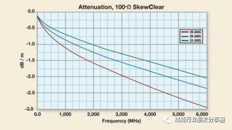
24, 26 and 28 are the typical 100Ω cable loss curves.
For high-quality cable assemblies, the NEXT measured in accordance with the “SFF-8410 – Specification for HSS Copper Testing and Performance Requirements” should be lower than 3%. As for the S-parameter, the NEXT should be greater than 28 dB.
Return loss
Return loss measures the magnitude of the energy reflected from the system or cable when a signal is injected. This reflected energy causes a decrease in the signal amplitude at the receiving end of the cable and can lead to signal integrity issues at the transmitting end, which in turn can cause electromagnetic interference problems for the system and system designers.
This return loss is caused by impedance mismatch in the cable components. Only by treating this problem very carefully can the impedance not change when the signal passes through sockets, plugs, and cable terminals, so as to minimize the impedance variation. The current SAS-4 standard updates the impedance value from ±10Ω in SAS-2 to ±3Ω. High-quality cables should maintain the requirement within the tolerance of the nominal 85 or 100 ± 3Ω, such as SFF-8639 with SATA 15P or MCIO 74 Pin Cable.
Skew distortion
In SAS cables, there are two types of skew distortion: between differential pairs and within differential pairs (signal integrity theory – differential signal). Theoretically, if multiple signals are input simultaneously at one end of the cable, they should reach the other end simultaneously. If these signals do not arrive simultaneously, this phenomenon is called cable skew distortion, or delay-skew distortion. For differential pairs, the skew distortion within the differential pair is the delay between the two conductors of the differential pair, while the skew distortion between differential pairs is the delay between two sets of differential pairs. Larger skew distortion within the differential pair can deteriorate the differential balance of the transmitted signal, reduce the signal amplitude, increase time jitter, and cause electromagnetic interference problems. For high-quality cables, the skew distortion within the differential pair should be less than 10 ps, such as SFF-8654 8i to SFF-8643 or Anti-misalignment Insertion cable.
Electromagnetic interference
There are many causes of electromagnetic interference problems in cables: poor shielding or no shielding, incorrect grounding method, unbalanced differential signals, and further, impedance mismatch is also a cause. For external cables, shielding and grounding are likely to be the two most important factors to be addressed, such as SFF-8087 with red mesh or Cooper mesh grounding cable.
Usually, external or electromagnetic interference shielding should be a dual shielding of metal foil and braided layer, with an overall coverage of at least 85%. At the same time, this shielding should be connected to the outer jacket of the connector, with a 360° complete connection. The shielding of individual differential pairs should be isolated from the external shielding, and their filtering lines should terminate at the system signal or DC ground to ensure unified impedance control for the connector and cable components, such as SFF-8654 8i Full Wrap anti-slash or Scoop-proof connector cable.
Post time: Aug-08-2025


