
Introduction to Type-C Connectors
USB Type-C has emerged as a dominant player in the market thanks to its connector advantages and is now on the verge of reaching the top. Its application in various fields is unstoppable. Apple's MacBook has made people recognize the convenience of the USB Type-C interface and also revealed the development trend of future devices. In the days to come, more and more USB Type-C devices will be launched. Undoubtedly, the USB Type-C interface will gradually become widespread and dominate the market in the next few years. Moreover, on mobile devices such as phones and tablets, it has several features that enable faster charging, higher data transfer speeds, and support for display output. It is more suitable as an output interface for mobile devices. Most importantly, there is a strong need for a universal interface to enhance the connectivity between various devices. These features may make the Type-C interface truly become the unified interface of the future, not just in the application fields you see!
If designed in accordance with the industry standards of the USB Association, the USB Type-C connector is bound to be fashionable, thin, and compact, suitable for mobile devices. At the same time, it needs to meet the high-strength requirements of the association and be suitable for various industrial applications. The USB Type-C connector provides a reversible plug interface; the socket can be inserted from any direction, achieving easy and reliable connection. This connector also needs to support multiple different protocols and can be backward compatible with HDMI, VGA, DisplayPort, and other connection types from a single C-type USB port through adapters. To address performance in electromagnetic interference (EMI) and other harsh environments, more design considerations are needed. It is recommended that manufacturers choose connector suppliers with TID certification to avoid problems in terminal applications!
The USB Type-C 3.1 interface has six major advantages:
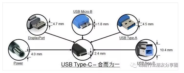
1) Full functionality: It supports data, audio, video, and charging simultaneously, laying the foundation for high-speed data, digital audio, high-definition video, fast charging, and multi-device sharing. One cable can replace multiple cables used before.
2) Reversible insertion: Similar to the Apple Lightning interface, the front and back of the port are the same, supporting reversible insertion.
3) Bidirectional transmission: Data and power can be transmitted in both directions.
4) Backward compatibility: Through adapters, it can be compatible with USB Type-A, Micro-B, and other interfaces.
5) Small size: The interface size is 8.3mm x 2.5mm, approximately one-third the size of a USB-A interface.
6) High speed: Compatible with the USB 3.1 protocol, it can support up to 10Gb/s data transmission, such as USB C 10Gbps and USB 3.1 Gen 2 standards, achieving ultra-fast transmission.
USB PD Communication Instructions
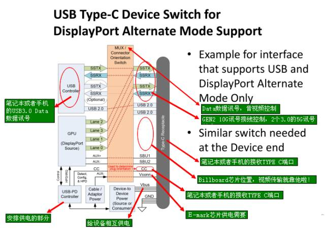
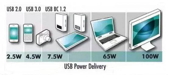
USB - Power Delivery (USB PD) is a protocol specification that enables simultaneous transmission of up to 100W of power and data communication over a single cable; USB Type-C is a completely new specification for a USB connector that can support a series of new standards such as USB 3.1 (Gen1 and Gen2), Display Port, and USB PD; the default maximum supported voltage and current for a USB Type-C port is 5V 3A; if USB PD is implemented in a USB Type-C port, it can support the 240W power defined in the USB PD specification, therefore, having a USB Type-C port does not mean it supports USB PD; USB PD seems to be just a protocol for power transmission and management, but in fact, it can change port roles, communicate with active cables, allow DFP to become the power supply device and many other advanced functions. Therefore, devices that support PD must use CC Logic chips (E-Mark chips), for example, using a 5A 100W USB C Cable can achieve efficient power supply.
USB Type-C VBUS Current Detection and Usage
The USB Type-C has added current detection and usage functions. Three new current modes have been introduced: the default USB power mode (500mA/900mA), 1.5A, and 3.0A. These three current modes are transmitted and detected through the CC pins. For DFPs that require broadcasting current output capability, different values of CC pull-up resistors Rp are needed to achieve this. For UFPs, the voltage value on the CC pin needs to be detected to obtain the current output capability of the other DFP.
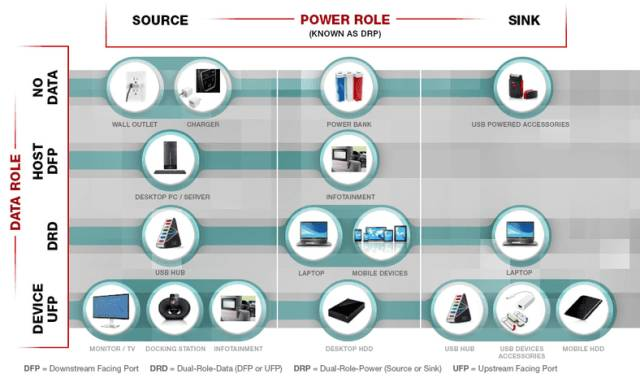
DFP-to-UFP and VBUS Management and Detection
DFP is a USB Type-C port located on the host or hub, connected to the device. UFP is a USB Type-C port located on the device or hub, connected to the host or hub's DFP. DRP is a USB Type-C port that can function as either DFP or UFP. DRP switches between DFP and UFP every 50ms in standby mode. When switching to DFP, there must be a resistor Rp pulling up to VBUS or an current source output on the CC pin. When switching to UFP, there must be a resistor Rd pulling down to GND on the CC pin. This switching action must be completed by the CC Logic chip.
VBUS can only be output when DFP detects the insertion of UFP. Once UFP is removed, VBUS must be turned off. This operation must be completed by the CC Logic chip.
Note: The above-mentioned DRP is different from USB-PD DRP. USB-PD DRP refers to the power ports that act as Power Source (provider) and Sink (consumer), for example, the USB Type-C port on a laptop supports USB-PD DRP, which can act as Power Source (when connecting a USB drive or mobile phone) or Sink (when connecting a monitor or power adapter).
DRP concept, DFP concept, UFP concept
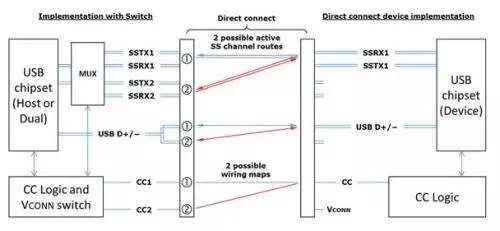
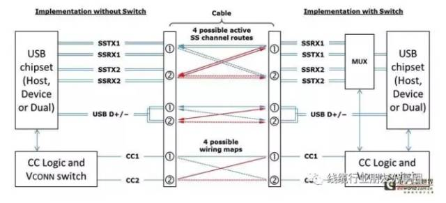
Data transmission mainly consists of two sets of differential signals, TX/RX. CC1 and CC2 are two key pins with many functions:
Detecting connections, distinguishing between front and back sides, distinguishing between DFP and UFP, which is the master-slave configuration for Vbus, there are two types of USB Type-C and USB Power Delivery.
Configuring Vconn. When there is a chip in the cable, one CC transmits a signal, and the other CC becomes the power supply Vconn. Configuring other modes, such as when connecting audio accessories, DP, PCIE, there are four power and ground lines for each, DRP (Dual Role Port): dual-role port, DRP can be used as DFP (Host), UFP (Device), or dynamically switch between DFP and UFP. A typical DRP device is a computer (the computer can act as a USB host or a device to be charged (Apple's new MacBook Air)), a mobile phone with OTG function (the mobile phone can act as a device to be charged and read data, or as a host to provide power or read data from a USB drive), a power bank (discharge and charging can be done through one USB Type-C, that is, this port can discharge and charge).
The typical host-client (DFP-UFP) implementation method of USB Type-C
CCpin concept
CC (Configuration Channel): Configuration Channel, this is a newly added key channel in USB Type-C. Its functions include detecting USB connections, detecting the correct insertion direction, establishing and managing the connection between USB devices and VBUS, etc.
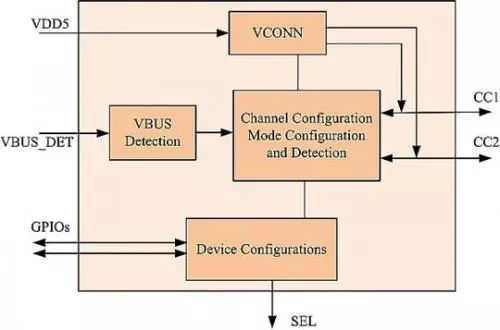
There is an upper pull-up resistor Rp on the CC pin of DFP, and a lower pull-down resistor Rd on UFP. When not connected, the VBUS of DFP has no output. After connection, the CC pin is connected, and the CC pin of DFP will detect the pull-down resistor Rd of UFP, indicating that the connection is made. Then, DFP will open the Vbus power switch and output power to UFP. Which CC pin (CC1, CC2) detects the pull-down resistor determines the insertion direction of the interface, and also switches RX/TX. The resistance Rd = 5.1k, and the resistance Rp is an uncertain value. According to the previous diagram, it can be seen that there are several power supply modes for USB Type-C. How to distinguish them? It is based on the value of Rp. The voltage detected by the CC pin is different when the value of Rp is different, and then control the DFP end to execute which power supply mode. It should be noted that the two CC pins drawn in the above figure are actually only one CC line in the cable without the chip.
Post time: Nov-03-2025


