
Today’s storage systems not only grow at terabits and have higher data transfer rates, but also require less energy and occupy a smaller footprint. These systems also need better connectivity to provide more flexibility. Designers need smaller interconnects to provide the data rates needed today or in the future. And a norm from birth to development and gradually mature is far from a day’s work. Especially in the IT industry, any technology is constantly improving and evolving itself, as is the Serial Attached SCSI (SAS) specification. As a successor to parallel SCSI, the SAS specification has been around for some time.
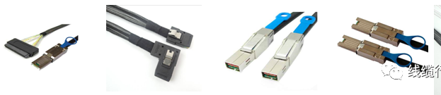
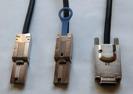
In the years that SAS has gone through, its specifications have been improved, although the underlying protocol has been retained, basically there are no too many changes, but the specifications of the external interface connector have undergone many changes, which is an adjustment made by SAS to adapt to the market environment, with these “incremental steps to a thousand miles” continuous improvement, SAS specifications have become increasingly mature. The interface connectors of different specifications are called SAS, and the transition from parallel to serial, from parallel SCSI technology to serial connected SCSI (SAS) technology has greatly changed the cable routing scheme. Previous parallel SCSI could operate single-ended or differential over 16 channels at up to 320Mb/s. At present, the SAS3.0 interface that is more common in the enterprise storage field is still used on the market, but the bandwidth is twice as fast as the SAS3 that has not been upgraded for a long time, which is 24Gbps, about 75% of the bandwidth of the common PCIe3.0×4 solid-state drive. The latest MiniSAS connector described in the SAS-4 specification is smaller and allows for higher density. The latest Mini-SAS connector is half the size of the original SCSI connector and 70% the size of the SAS connector. Unlike the original SCSI parallel cable, both SAS and Mini SAS have four channels. However, in addition to higher speed, higher density, and more flexibility, there is also an increase in complexity. Because of the smaller size of the connector, the original cable manufacturer, cable assembler, and system designer must pay close attention to signal integrity parameters throughout the cable assembly.
Not all cable assemblers are able to provide high-quality high-speed signals to meet the signal integrity needs of storage systems. Cable assemblers need high quality and cost-effective solutions for the latest storage systems. In order to produce stable, durable high-speed cable assemblies, several factors need to be considered. In addition to maintaining the quality of machining and processing, designers need to pay close attention to the signal integrity parameters that make today’s high-speed memory device cables possible.
Signal integrity specification (What signal is complete?)
Some of the main parameters of signal integrity include insertion loss, near-end and far-end crosstalk, return loss, skew distortion of the difference pair internally, and the amplitude of difference mode to common mode. Although these factors are interrelated and influence each other, we can consider one factor at a time to study its main impact.
Insertion loss (High frequency parameters Basics 01- attenuation parameters)
The insertion loss is the loss of signal amplitude from the transmitting end of the cable to the receiving end, which is directly proportional to the frequency. The insertion loss also depends on the wire number, as shown in the attenuation diagram below. For short range internal components of a 30 or 28-AWG cable, a good quality cable should have less than 2dB/m attenuation at 1.5GHz. For external 6Gb/s SAS using 10m cables, a cable with an average line gauge of 24 is recommended, which has only 13dB attenuation at 3GHz. If you want more signal margin at higher data rates, specify a cable with less attenuation at high frequencies for longer cables.
Crosstalk (High Frequency Parameters Basics 03- Crosstalk parameters)
The amount of energy transmitted from one signal or difference pair to another. For SAS cables, if the near-end crosstalk (NEXT) is not small enough, it will cause most link problems. NEXT’s measurement is made at only one end of the cable, and it is the amount of energy transferred from the output transmission signal pair to the input receiving pair. Far-end crosstalk (FEXT) is measured by injecting a signal for the transmission pair at one end of the cable and observing how much energy remains on the transmission signal at the other end of the cable
The NEXT in the cable assembly and connector is usually caused by poor isolation of the signal differential pairs, which may be caused by outlets and plugs, incomplete grounding, or poor handling of the cable termination area. The system designer needs to ensure that the cable assembler has addressed these three issues.
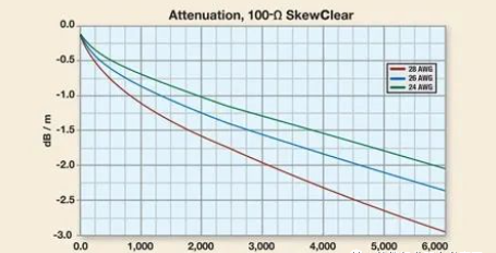
Loss curves for common 100Ω cables of 24, 26, and 28
Good quality cable assembly in accordance with the “SFF-8410-Specification for HSS Copper Testing and Performance Requirements” measured NEXT should be less than 3%. As far as the s-parameter is concerned, NEXT should be greater than 28dB.
Return Loss (High Frequency Parameters Basics 06- Return Loss)
Return loss measures the amount of energy reflected from a system or cable when a signal is injected. This reflected energy can cause a drop in signal amplitude at the receiving end of the cable and can cause signal integrity problems at the transmitting end, which can cause electromagnetic interference problems for the system and system designers.
This return loss is caused by impedance mismatches in the cable assembly. Only by treating this problem with great care can the impedance of the signal not change when it passes through the socket, plug and wire terminal, so that the impedance change is minimized. The current SAS-4 standard is updated to the impedance value of ±3Ω compared with the ±10Ω of SAS-2, and the requirements of good quality cables should be kept within the nominal tolerance of 85 or 100±3Ω.
Skew distortion
In SAS cables, there are two skew distortions: between difference pairs and within difference pairs (the difference signal of signal integrity theory). In theory, if multiple signals are entered at one end of the cable, they should arrive at the other end simultaneously. If these signals do not arrive at the same time, this phenomenon is called skew distortion of the cable, or delay-skew distortion. For difference pairs, the skew distortion inside the difference pair is the delay between the two wires of the difference pair, and the skew distortion between the difference pairs is the delay between the two sets of difference pairs. The large skew distortion of the difference pair will worsen the difference balance of the transmitted signal, reduce the signal amplitude, increase the time jitter and cause electromagnetic interference problems. The difference of a good quality cable to the internal skew distortion should be less than 10ps
Post time: Nov-30-2023


